Can
we work any dx with a vertical ?
An experience.
by
ik3umt
This article has been update on September 10th
2009, further links at the end of page.
Introduction
My ham
activity has always been DX on HF bands.
In 2007 I
had to move my shack on QTH were I actually live.
With
awareness of urban/environmental trouble of my new QTH (naturalistic territory
into protected green area)
also not of my exclusive property, I decided no more to install
my old antenna system composed by an Optibeam OB17-4
and a Cushcraft A3WS plus some wire antennas,
but to inaugurate new area with a multiband vertical , aware of performance I would have
obtained.
Which antenna
?
The choice
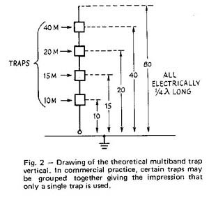
of which vertical, was dictated by my own will to not have conventional traps.
They work as RF switches , thus leaving that the
portion of the antenna in use is physically from feedpoint
to trap in use for the determined band.
Also, as we reduce
frequency, further inductance is added by higher frequency traps
So, the
choice is fell on two candidates, the
STEPPIR BigIR and BUTTERNUT HF-9V
First one
is a motorized
vertical remotely extendible which allows to work on every band with the best
length of radiator and then an almost perfect match.
The second
one is a multiband vertical with a particular
arrangement of low loss inductors and capacitors which allows the stylus to
work on any band for the entirety of its size.
Given the
relatively high cost of STEPPIR, and the inevitable presence of certain time
waiting for the band changing due to motorized variation of its length, I opted
for purchase of a new BUTTERNUT HF-9V having also quality evidence on the same
brand antennas already used by me.
My
experience here reported can be anyway applied to any model and brand of quarterwave vertical antenna , my
intention is surely not to advertise either manufacturers.
Installation
The
installation goal was been to obtain the best made possible antenna system to
bring, match or even exceed the performance of my previous antenna system.
The first step was to work on a ground plane as efficient as conditions allow.
The efficiency of a vertical antenna is proportional to its ground plane efficiency.
There are countless articles and publications about this, but truth coming out is always same.
A vertical with a poor ground plane (simple rod planted on ground, a bunch of radials lying at less
worse, 10 squared feet counterpoise) will probably allow you to work many DX in
good conditions of propagation and band crowding, but there will be many more
stations you will not able to work.
It depends as usual by assessment used: If you tried efficient antennas
there'll soon realise, if it is first antenna you ever used ,
also a piece of wire thrown from the balcony will make you enthusiastic.
Anyway, this is not the matter to approach to a superficial installation.
When
installing a ground plane antenna, one wonders :
“ground mounted or elevated antenna ?”
Here too
many theories and pages were consumed.
Often
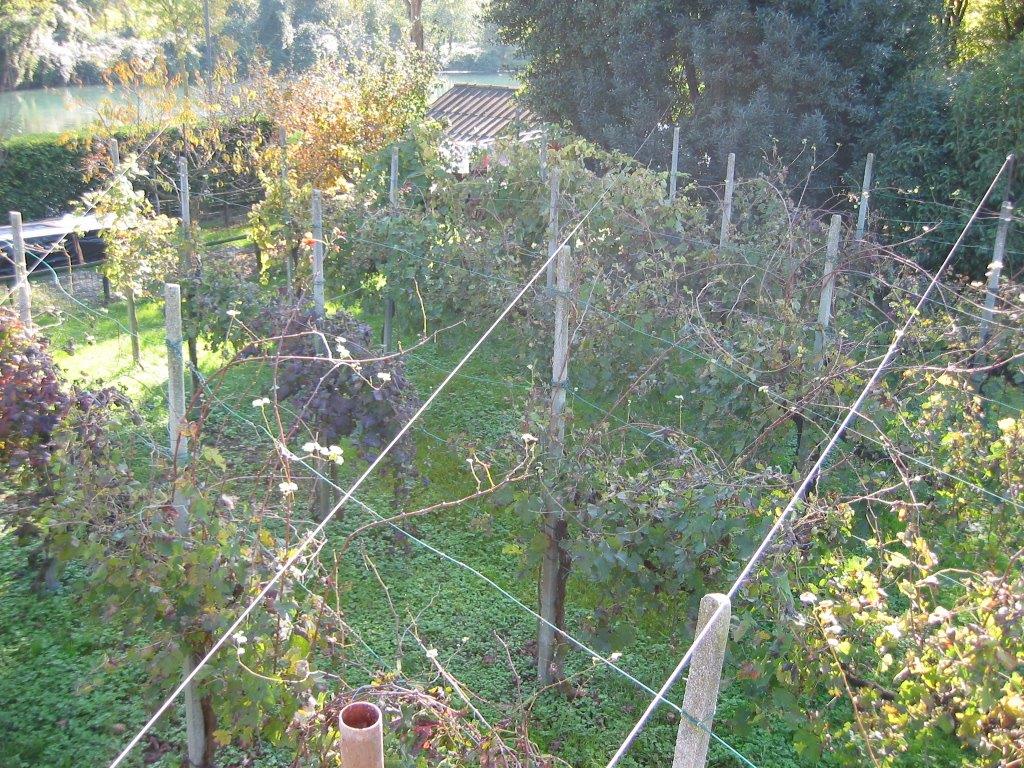
choice is forced (buildings, condominium etc.). In my case the limitation on
the bare earth was the existence of a vineyard with a web of tie-rod steel for
its guying, surely source of interaction with the radiating element.
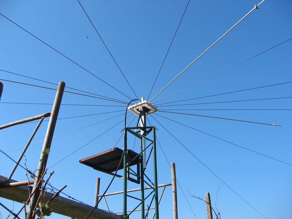
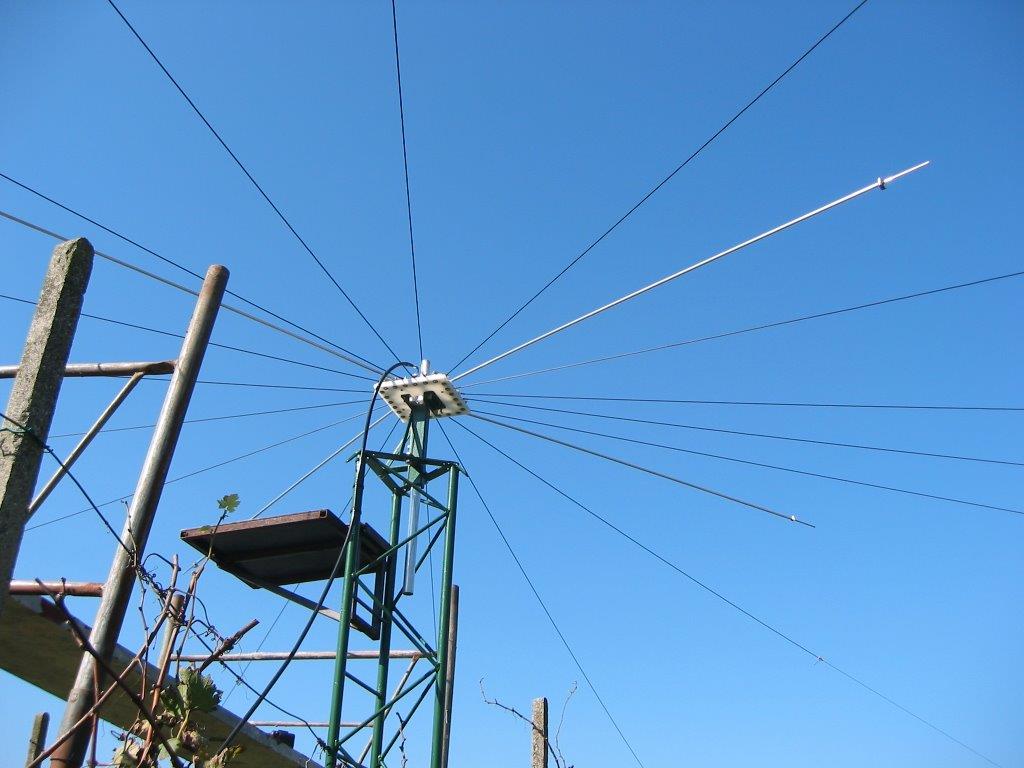
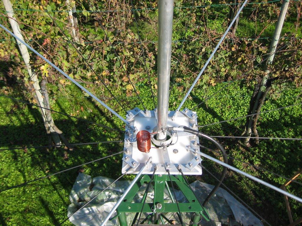
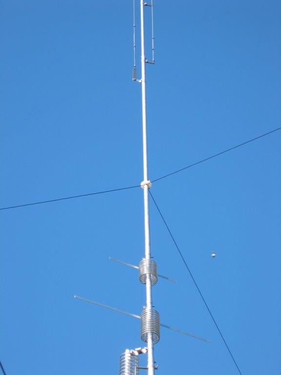
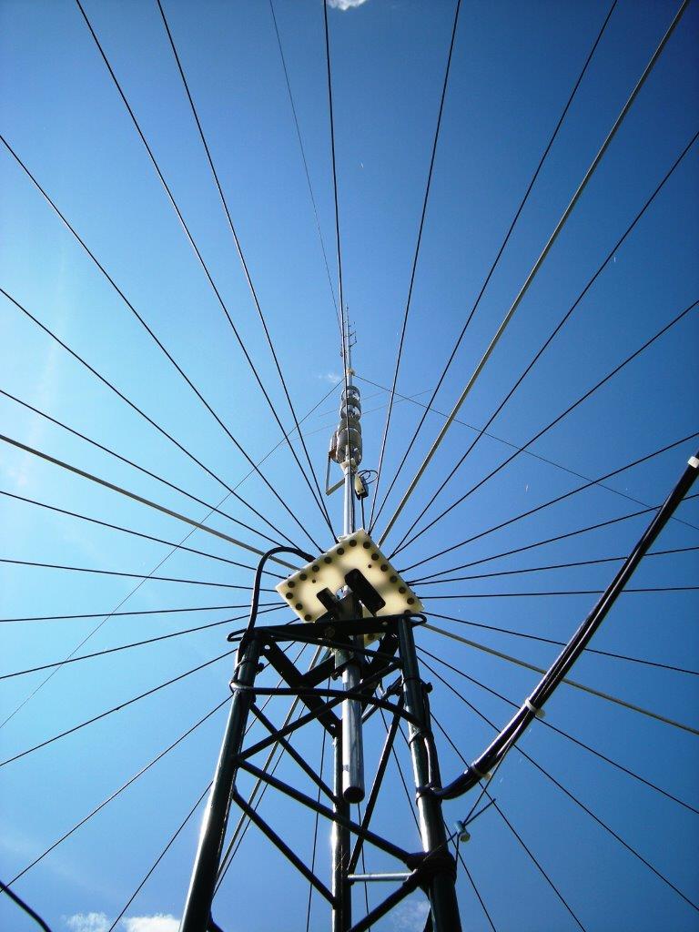
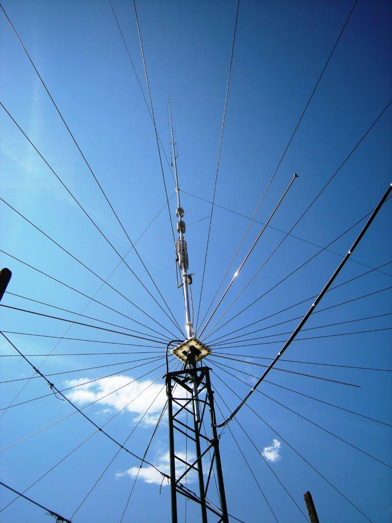
The installation was then carried on top of a 10ft tower to bring the whole
system beyond anything interfering.
After
some documentation on the issue and some analysis to computer simulation
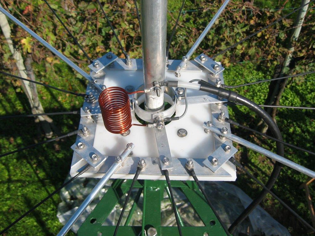
software I decided to install 2 resonant radial for each band, arranged radially opposed (180 °) one another, calculating the
length each with the well-known formula Length (ft) = 234 / Frequency (MHz).
The opposite provision of 2 radial for each band allows to
obtain a sufficiently omnidirectional
radiation lobe.
To
achieve radials I used wire from monopolar electrical
installations with 1.5 squared millimetres (15AWG) section at which end was
installed a plastic tie-clip
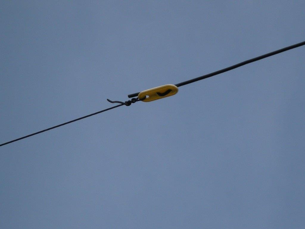
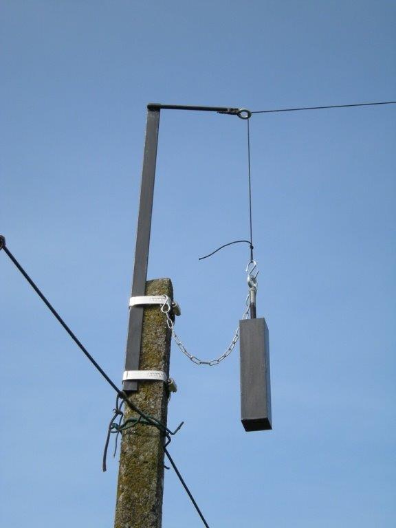
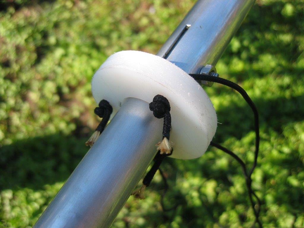
To
maintain constant tension of radial I used a counterweight of about 1Kg that
using a nylon cord held, knotted to plastic clip and passing through special
brackets I built, has taken steps to function.
A chain with appropriate galvanized staples warrant
the counterweight clamp in case of nylon wire breaks.
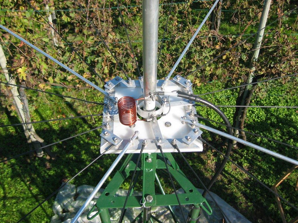
Two
80mt radials, being rather lengthy, are maintained by a
This method provides a set of radial free from the pressures of strong wind and
aesthetically always in order.
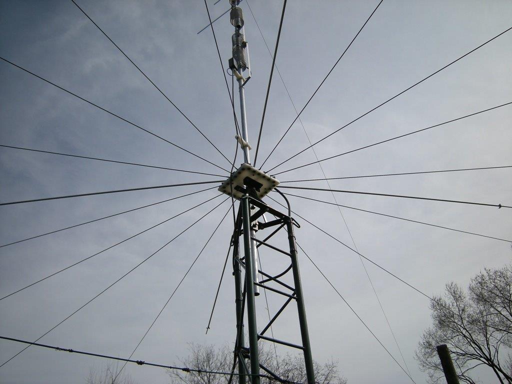
For
The radial were distributed in 360 ° with the following order to avoid band
interactions
80m 15m 30m 12m 6m 40m 17m 20m 10m 6m 80m 15m 30m 12m 6m 40m 17m 20m 10m 6m
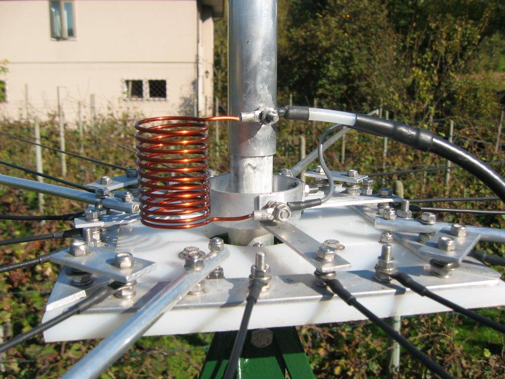
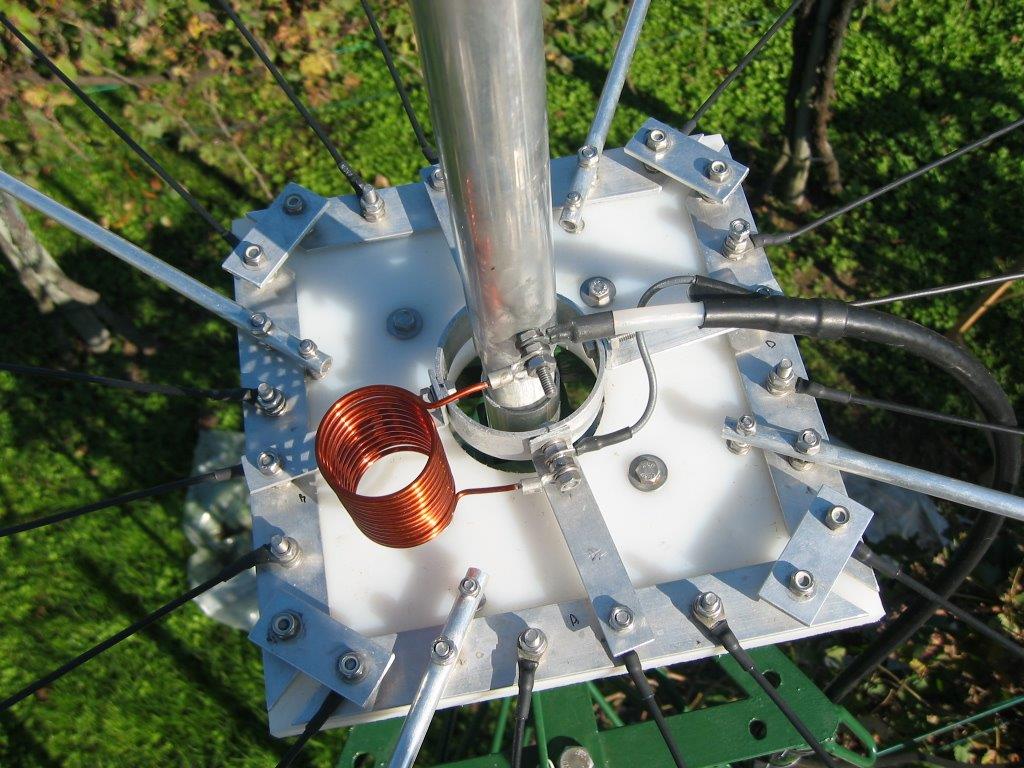
Contrary to a ground installation an elevated radials system should not be
connected to earth or a metal plate (tower) in his ground common point ,whole system will be detuned otherwise.
Therefore, I have adopted a common ground plate, achieved by insulating
polyethylene panel used to support a flat aluminium profile on which radials
were locked.
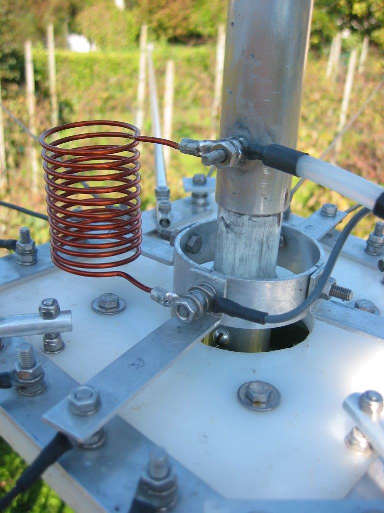
Then, this
ground “ring” has been electrically kept further closer to the feedpoint to reduce electrical
path to radials and more evenly distribute currents.
Ground plane height
A
particular note about height of ground plane:
I prepared system to facilitate laborious tuning acting on the radials length;
contrary to what I originally thought, the exact radial cutting to get resonance
is effective only for a system whose height from ground is more than ¼ wave at
considered frequency (the lowest in case
of a multiband).
Therefore, on 80mt elevated resonant radials system, is “elevated” only for
heights of 65ft or more above ground level .
What
happens then if radials are not "really" elevated ?
In my case (10ft), ground plane is 1 / 26 wave from ground in 80mt, 1 / 13 wave
in 40, 1 / 7 wave in 20mt and so on.
The "surprise" I found during calibration was to not have any variation
of resonance frequency
when I went to vary the length of radials, either lengthening or
shortening
This is dued to capacitive interaction that occurs
between radial and the ground below (which in my case is rather conductive) as
well as between radials themselves, this phenomenon detunes further the ground
system.
It
anyway continues effectively its native function.
The antenna in fact did not submit large calibration deviations from manual
specifications.
Once
implemented ground plane, I then proceeded assembling as textbook.
Some hints
Some
electrical / mechanical hints :
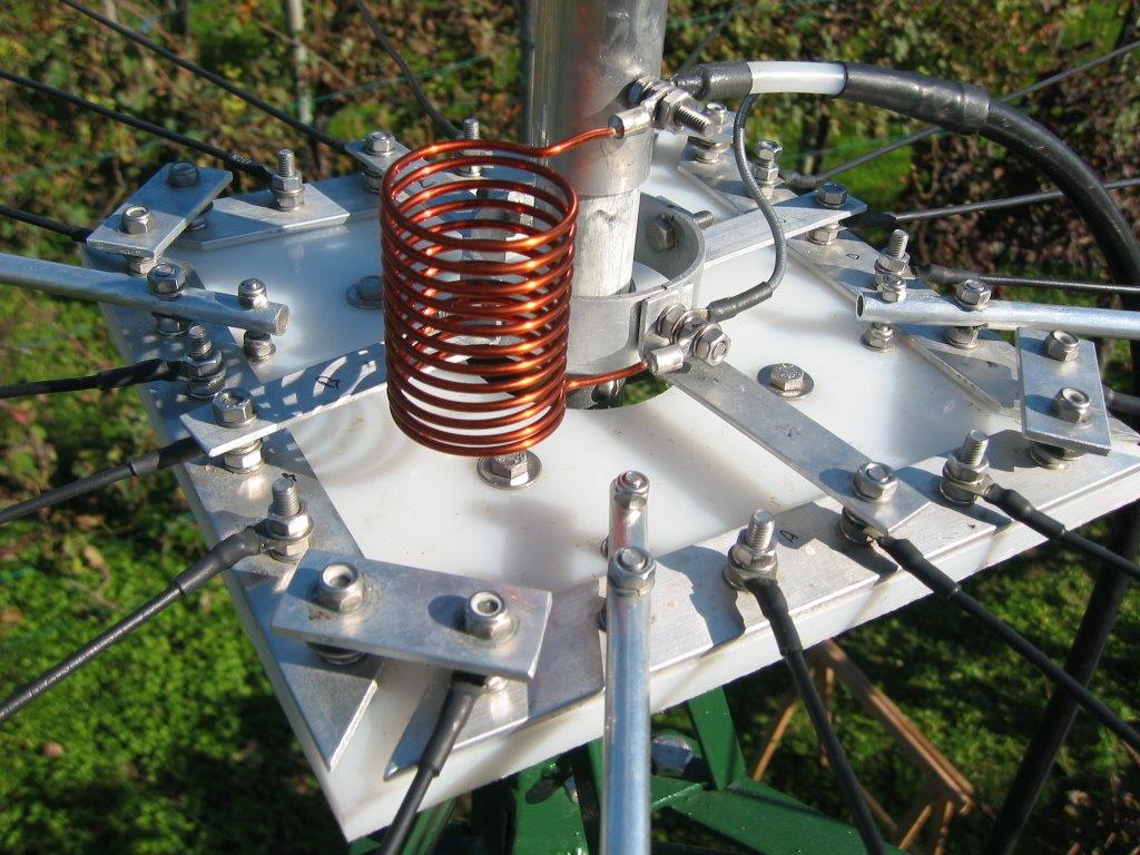
All joints
between pipes and conductive elements generally were treated with zinc oxide
paste Penetrox A-13 to maintain the effectiveness
conductivity and repellence to oxidation.
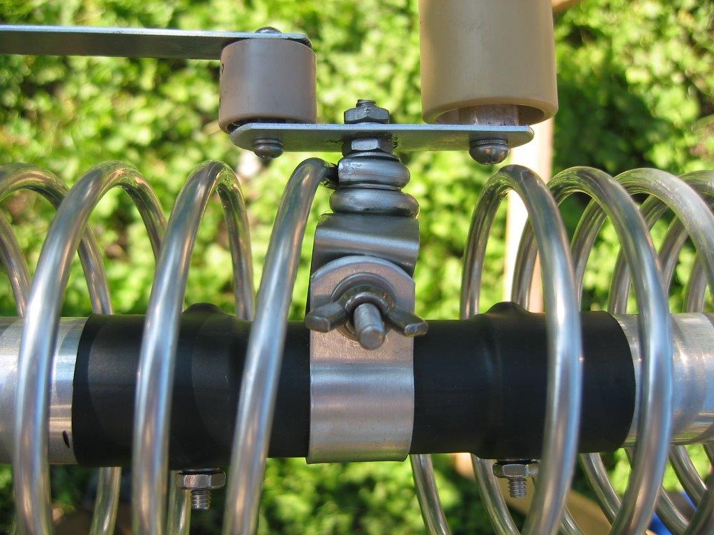
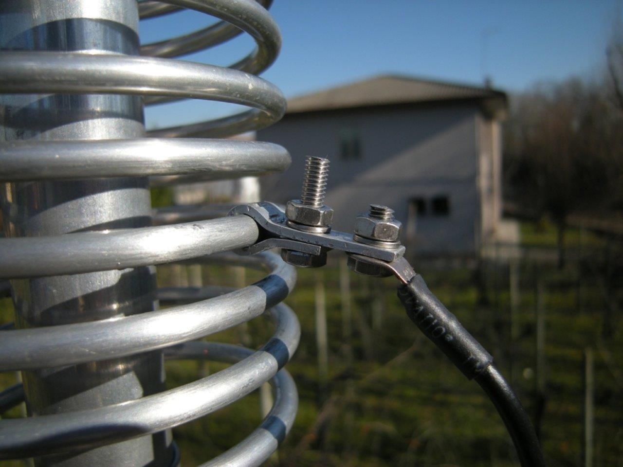
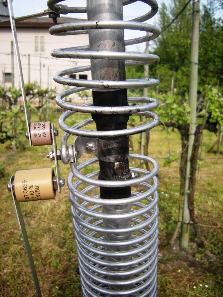
As for the HF-2V and HF-6V, the capacitors connection strip can present discharge
arc danger, between the extremities of each of two 1-1/8” pipes and the strip
itself in presence of moisture and high power.
I then proceeded to isolate the point of attachment with thick thermoretracting sheath.
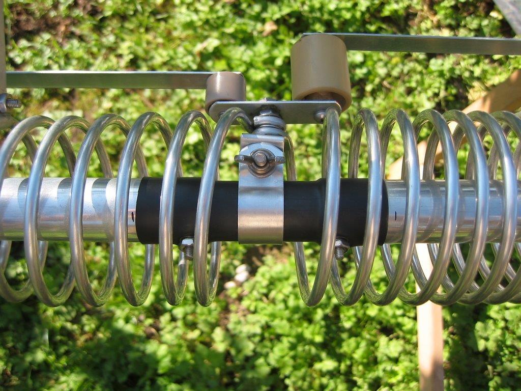
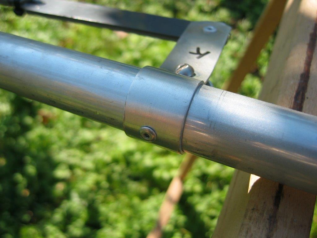
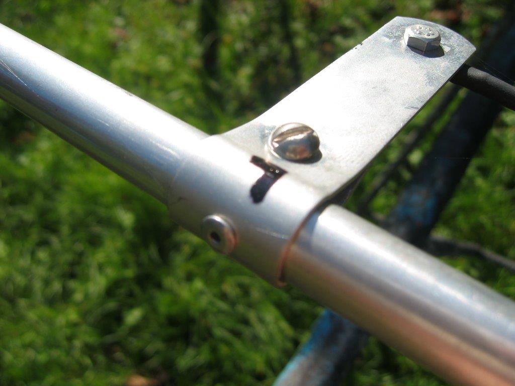
Locking
stubs straps tend, as with other brands and models of American antennas (must
be a bad habit design), to slide on pipes even if bolts are tightened to
maximum.
I have solved the problem by aluminium rivets, applied of course only on fixed straps
(the ones not subject to adjustment for calibration)
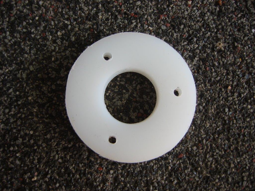
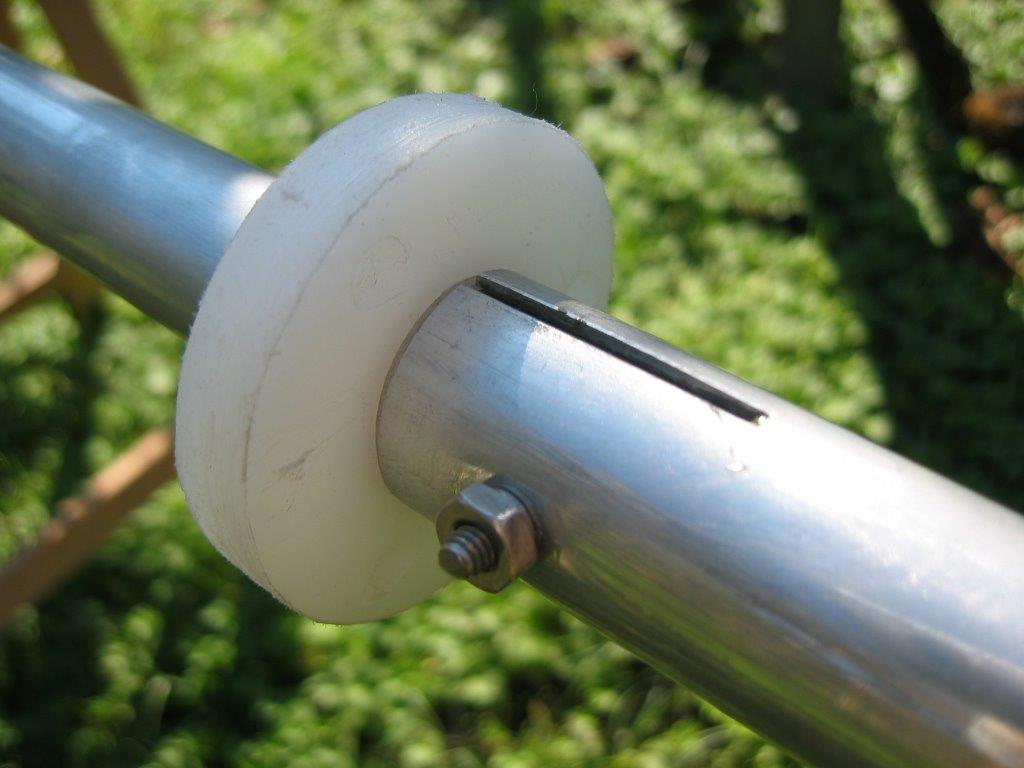
Guying
Butternut,
considering stylus flexibility, does not consider it necessary antenna guying,
but I strongly advice it ,having personally seen the
amount of force exerted by a strong wind on guyed antenna.
Surely it would be broken at its base unless it had been.
I’ve created for the purpose a polyethylene ring with a 7/8” inner diameter, sliding
it on the same diameter pipe so that hang from edge of
The ring has been drilled to allow anchorage of 3 Kevlar guy wires.
.
Tuning
:
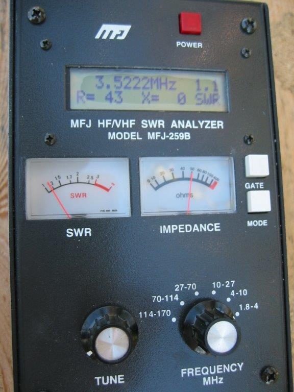
Tuning is rather
laborious because of its 9 bands and many action points, but help of a tool
like MFJ259B has made it quite amusing.
Settings of lower bands influence slightly some higher bands.
Tuning was then done, as textbook, in
the following band order:
80m 40m 20m 15m 10m 30m 17m 12m 6m
and retuned again in the same order with fine adjustments for the best result.
The final results of SWR, reported with MFJ 259B connected to antenna feedpoint (including RJ11 75ohm stub) ,
are as follows:
|
BANDA |
|
F LOW |
R |
X |
SWR |
|
F MID |
R |
X |
SWR |
|
F HIGH |
R |
X |
SWR |
|
|
|
|
|
|
|
|
|
|
|
|
|
|
|
|
|
|
80 |
|
3,500 |
120 |
0 |
2,2 |
|
3,522 |
43 |
0 |
1,1 |
|
3,548 |
28 |
17 |
2 |
|
40 |
|
7,000 |
35 |
23 |
1,9 |
|
7.093 |
37 |
0 |
1,1 |
|
7,200 |
76 |
20 |
2,1 |
|
30 |
|
10.100 |
36 |
0 |
1,2 |
|
10,113 |
40 |
0 |
1,2 |
|
10,150 |
58 |
14 |
1,3 |
|
20 |
|
14,000 |
26 |
0 |
1,7 |
|
14,178 |
29 |
0 |
1,5 |
|
14,350 |
30 |
8 |
1,7 |
|
17 |
|
18,060 |
112 |
10 |
2,5 |
|
18,120 |
44 |
38 |
2,4 |
|
18,168 |
23 |
25 |
2,5 |
|
15 |
|
21,000 |
75 |
0 |
1,5 |
|
21,190 |
38 |
0 |
1,1 |
|
21,450 |
27 |
0 |
1,7 |
|
12 |
|
24,890 |
31 |
0 |
1,5 |
|
24,930 |
31 |
0 |
1,5 |
|
24,990 |
21 |
0 |
1,9 |
|
10 |
|
28,000 |
87 |
16 |
1,8 |
|
28,715 |
46 |
0 |
1 |
|
29,500 |
67 |
19 |
2 |
|
6 |
|
50,000 |
60 |
2 |
1,2 |
|
50,415 |
43 |
0 |
1,1 |
|
51,00 |
37 |
7 |
1,3 |
Where
F LOW means the lowest band edge frequency in MHz , F MID the minimum SWR point and F HIGH the
highest band edge frequency or where SWR is equal to 2.00
The only band suffering more was 17m where hasn’t been possible to obtain an
SWR better than 2.4
Anyway I remember you SWR value is NOT index of radiation effectiveness but
only of transmission line match.
First contact made on 17m has shown truth, connecting 5N8NDP in
80mt problem
How
manual says, 80m band is very narrow (about 50 KHz) and allows the use of first
CW portion of 80mt , (my tuning choice in this case)
What
then to do in order to exploit more 80mt portions ?
Idea is rather intuitively: short-circuit some 80m inductor turns bringing in
resonance the working frequency, raising it, by mean of relays.
Using 2 relays is possible to add two 50 KHz portions to HF9V, above the
resonance frequency chosen as initial.
The same system can work in any similar antenna as well as for any frequency.
Schematic to use is the following one:
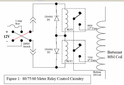
The
lack of power leaves original circuit intact, powering to 12Vcc with a certain polarity
will active a relay, feeding a reverse polarity will de-active this relay and active
the other one causing required turns to be shortened in order to increase resonance
frequency.
So, cable used is just a 2-conductor type.
In my particular case I used the RLY2 relay for the CW portion with a 1:2 SWR within
3,550 to 3,6 MHz, and RLY1 relay for the SSB portion with a 1:2
SWR within the 3,750 to 3,800 MHz.
The circuit has been carried out within a sealed plastic minibox
for electronic assembly, directly locked by mean of a polyethylene arm to
radiant element near 80m inductor base.
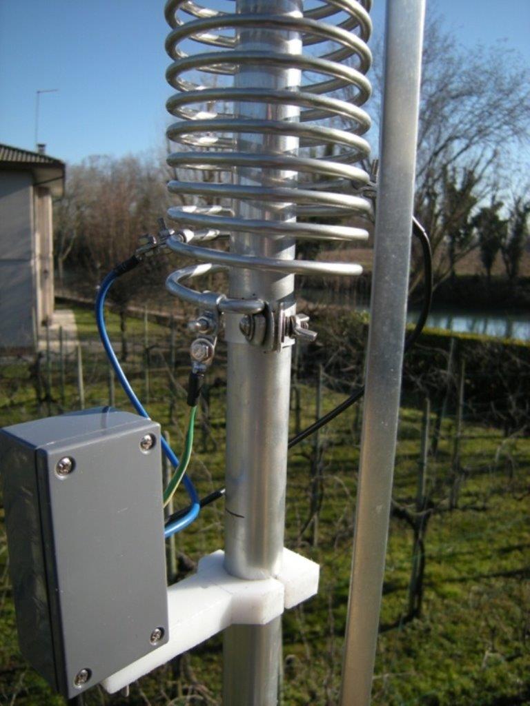
Inductor
tuning straps was made by aluminium and tightened with stainless steel bolts.
After
appropriate straps tuning, the best SWR results obtained through the operation
of each relay were as follows:
|
BANDA |
|
F LOW |
R |
X |
SWR |
|
F MID |
R |
X |
SWR |
|
F HIGH |
R |
X |
SWR |
|
|
|
|
|
|
|
|
|
|
|
|
|
|
|
|
|
|
80 CW2 |
|
3,533 |
20 |
0 |
2 |
|
3,562 |
45 |
1 |
1 |
|
3,590 |
108 |
0 |
2 |
|
80 SSB |
|
3,720 |
20 |
0 |
2 |
|
3,768 |
41 |
0 |
1 |
|
3,813 |
47 |
27 |
2 |
Does it work ???
About
antenna radiation efficiency, instrumental testing would be very complicated, anyway first QSOs give a good perspective of functionality.
This is an extract of the first hundred or so QSO from my log, all made with
this antenna (with aid in some cases of maximum power here allowed of 500W):
|
EK8PL |
ARMENIA |
31/03/2008 |
20:56 |
80m |
SSB |
59 |
59 |
|
LY1GN |
LITHUANIA |
31/03/2008 |
21:38 |
80m |
SSB |
59 |
59 |
|
EA6/EA5KA |
BALEARIC IS. |
31/03/2008 |
21:24 |
80m |
SSB |
59 |
59 |
|
9K2HS |
KUWAIT |
31/03/2008 |
23:48 |
40m |
SSB |
59 |
59 |
|
5B/LZ2HM |
CYPRUS |
31/03/2008 |
23:26 |
80m |
SSB |
59 |
59 |
|
OZ/DL1TM |
DENMARK |
03/04/2008 |
21:12 |
80m |
SSB |
59 |
59 |
|
SP75T |
POLAND |
03/04/2008 |
21:20 |
80m |
SSB |
59 |
59 |
|
EC7AKV |
SPAIN |
07/04/2008 |
20:10 |
40m |
SSB |
59 |
59 |
|
W1GUS |
U.S.A. |
07/04/2008 |
20:42 |
20m |
SSB |
59 |
59 |
|
YK9G |
SYRIA |
10/04/2008 |
22:14 |
80m |
CW |
599 |
599 |
|
3Z10UM |
POLAND |
10/04/2008 |
22:18 |
80m |
CW |
599 |
599 |
|
OZ8CTH |
DENMARK |
10/04/2008 |
12:46 |
20m |
SSB |
59 |
59 |
|
VR10XMT |
HONG KONG |
10/04/2008 |
13:44 |
20m |
RTTY |
599 |
599 |
|
YK9G |
SYRIA |
10/04/2008 |
20:57 |
30m |
CW |
599 |
599 |
|
A71BX |
QATAR |
11/04/2008 |
11:44 |
17m |
CW |
599 |
599 |
|
YK9G |
SYRIA |
11/04/2008 |
11:59 |
15m |
CW |
599 |
599 |
|
YK9G |
SYRIA |
11/04/2008 |
12:50 |
17m |
CW |
599 |
599 |
|
3B8MM |
MAURITIUS
I. |
11/04/2008 |
20:30 |
40m |
CW |
599 |
599 |
|
OX3KQ |
GREENLAND |
11/04/2008 |
20:51 |
40m |
SSB |
59 |
59 |
|
A45XR |
OMAN |
11/04/2008 |
20:52 |
30m |
CW |
599 |
599 |
|
V63JQ |
MICRONESIA |
11/04/2008 |
21:31 |
30m |
CW |
599 |
599 |
|
JX9JKA |
JAN MAYEN |
11/04/2008 |
21:45 |
40m |
SSB |
59 |
59 |
|
HG25STT |
HUNGARY |
11/04/2008 |
21:48 |
80m |
CW |
599 |
599 |
|
UN12B |
KAZAKHISTAN |
11/04/2008 |
21:54 |
40m |
CW |
599 |
599 |
|
TI8/DL4MO |
COSTA
RICA |
11/04/2008 |
22:05 |
30m |
CW |
599 |
599 |
|
YK9G |
SYRIA |
11/04/2008 |
22:32 |
40m |
CW |
599 |
599 |
|
3B8/SP2JMB |
MAURITIUS
I. |
11/04/2008 |
22:58 |
80m |
CW |
599 |
599 |
|
3B8MM |
MAURITIUS
I. |
11/04/2008 |
23:11 |
80m |
CW |
599 |
599 |
|
XU7KOH |
KAMPUCHEA
(CAMBODIA) |
11/04/2008 |
23:17 |
40m |
CW |
599 |
599 |
|
3B8MM |
MAURITIUS
I. |
12/04/2008 |
12:57 |
12m |
CW |
599 |
599 |
|
YK9G |
SYRIA |
12/04/2008 |
13:13 |
15m |
CW |
599 |
599 |
|
PJ5NA |
SINT
MAARTEN |
12/04/2008 |
21:15 |
30m |
CW |
599 |
599 |
|
CO8LY |
CUBA |
12/04/2008 |
21:21 |
30m |
PSK |
59 |
59 |
|
VE1DX |
CANADA |
12/04/2008 |
22:21 |
30m |
CW |
599 |
599 |
|
WP3C |
PUERTO
RICO |
13/04/2008 |
21:15 |
30m |
RTTY |
599 |
599 |
|
ZF1DX |
CAYMAN IS. |
13/04/2008 |
22:09 |
20m |
CW |
599 |
599 |
|
HK4CZE |
COLOMBIA |
13/04/2008 |
22:23 |
30m |
CW |
599 |
599 |
|
FJ5DX |
SAINT
BARTHELEMY |
13/04/2008 |
22:26 |
20m |
RTTY |
599 |
599 |
|
ZV5R |
BRAZIL |
14/04/2008 |
21:39 |
40m |
CW |
599 |
599 |
|
K2SEW |
U.S.A. |
14/04/2008 |
21:54 |
30m |
CW |
599 |
599 |
|
OX3XR |
GREENLAND |
14/04/2008 |
21:58 |
30m |
CW |
599 |
599 |
|
WP4O |
PUERTO
RICO |
14/04/2008 |
22:04 |
20m |
CW |
599 |
599 |
|
VC2CQ |
CANADA |
14/04/2008 |
22:20 |
40m |
CW |
599 |
599 |
|
HZ1IK |
SAUDI
ARABIA |
16/04/2008 |
21:41 |
40m |
SSB |
59 |
59 |
|
JY4NE |
JORDAN |
16/04/2008 |
21:43 |
80m |
CW |
599 |
599 |
|
9Q1EK |
DEMOCRATIC
REPUBLIC OF CONGO |
16/04/2008 |
21:58 |
20m |
CW |
599 |
599 |
|
VE1AI |
CANADA |
16/04/2008 |
22:22 |
40m |
CW |
599 |
599 |
|
FM/I2GPT |
MARTINIQUE |
16/04/2008 |
22:23 |
30m |
CW |
599 |
599 |
|
SV5/SM8C |
DODECANESE
IS. |
16/04/2008 |
22:37 |
40m |
CW |
599 |
599 |
|
YN4SU |
NICARAGUA |
16/04/2008 |
22:39 |
40m |
CW |
599 |
599 |
|
VP8CMH/MM |
FALKLAND IS. |
16/04/2008 |
22:55 |
40m |
CW |
599 |
599 |
|
WP3B |
PUERTO
RICO |
16/04/2008 |
22:59 |
40m |
CW |
599 |
599 |
|
RA2FF |
KALININGRAD |
18/04/2008 |
20:20 |
30m |
CW |
599 |
599 |
|
4S7DXG |
SRI LANKA |
18/04/2008 |
20:27 |
40m |
CW |
599 |
599 |
|
E74OW |
BOSNIA-HERCEGOVINA |
18/04/2008 |
20:28 |
80m |
CW |
599 |
599 |
|
SU9NC |
EGYPT |
18/04/2008 |
21:38 |
40m |
CW |
599 |
599 |
|
9K2HN |
KUWAIT |
18/04/2008 |
21:40 |
80m |
CW |
599 |
599 |
|
UA2FR |
KALININGRAD |
18/04/2008 |
22:07 |
80m |
CW |
599 |
599 |
|
ET3JA |
ETHIOPIA |
18/04/2008 |
22:21 |
40m |
CW |
599 |
599 |
|
EK6LP |
ARMENIA |
18/04/2008 |
22:55 |
40m |
CW |
599 |
599 |
|
ZP8VAO |
PARAGUAY |
19/04/2008 |
20:29 |
20m |
SSB |
59 |
59 |
|
4Z60BS |
ISRAEL |
19/04/2008 |
20:49 |
80m |
CW |
599 |
599 |
|
4X0X |
ISRAEL |
19/04/2008 |
20:50 |
80m |
CW |
599 |
599 |
|
FJ/DJ2VO |
SAINT
BARTHELEMY |
19/04/2008 |
21:37 |
20m |
CW |
599 |
599 |
|
CO8LY |
CUBA |
19/04/2008 |
22:21 |
30m |
CW |
599 |
599 |
|
FJ/DJ2VO |
SAINT
BARTHELEMY |
19/04/2008 |
22:24 |
30m |
CW |
599 |
599 |
|
CN8ZG |
MOROCCO |
20/04/2008 |
17:30 |
20m |
SSB |
59 |
59 |
|
4S7DXG |
SRI LANKA |
20/04/2008 |
20:28 |
80m |
CW |
599 |
599 |
|
TF3ARI |
ICELAND |
20/04/2008 |
21:34 |
40m |
SSB |
59 |
59 |
|
5U5U |
NIGER |
20/04/2008 |
21:58 |
40m |
SSB |
59 |
59 |
|
GB0U |
GUERNSEY
& DEPENDENCIES |
22/04/2008 |
12:18 |
30m |
RTTY |
599 |
599 |
|
MU0FAL |
GUERNSEY
& DEPENDENCIES |
22/04/2008 |
12:31 |
20m |
CW |
599 |
599 |
|
9K2YM/P |
KUWAIT |
22/04/2008 |
13:12 |
20m |
RTTY |
599 |
599 |
|
VQ9LA |
CHAGOS ARCHIPELAGO |
22/04/2008 |
13:16 |
17m |
CW |
599 |
599 |
|
KP2YL |
AMERICAN
VIRGIN IS. |
22/04/2008 |
20:06 |
17m |
SSB |
59 |
59 |
|
ET3JA |
ETHIOPIA |
22/04/2008 |
20:12 |
30m |
CW |
599 |
599 |
|
CE3/VE7SV |
CHILE |
22/04/2008 |
21:26 |
20m |
CW |
599 |
599 |
|
HK4CZE |
COLOMBIA |
22/04/2008 |
21:52 |
20m |
CW |
599 |
579 |
|
A45WD |
OMAN |
22/04/2008 |
22:39 |
30m |
CW |
599 |
599 |
|
VK6HD |
AUSTRALIA |
22/04/2008 |
22:51 |
80m |
CW |
599 |
599 |
|
A71AN |
QATAR |
23/04/2008 |
11:59 |
15m |
CW |
599 |
599 |
|
GM3POI |
SCOTLAND |
23/04/2008 |
12:34 |
20m |
RTTY |
599 |
599 |
|
V51AS |
NAMIBIA |
23/04/2008 |
12:42 |
10m |
SSB |
57 |
55 |
|
G6PZ |
ENGLAND |
23/04/2008 |
20:24 |
40m |
CW |
599 |
599 |
|
ZD7X |
ST.HELENA I. |
23/04/2008 |
20:28 |
17m |
CW |
599 |
599 |
|
9M6/LA6VM |
SPRATLY
ARCHIPELAGO |
23/04/2008 |
20:30 |
40m |
CW |
599 |
599 |
|
YU8AU |
REPUBLIC
OF SERBIA |
24/04/2008 |
21:10 |
30m |
CW |
599 |
599 |
|
EK6TA |
ARMENIA |
24/04/2008 |
21:46 |
40m |
SSB |
59 |
59 |
|
HC2SL |
ECUADOR |
25/04/2008 |
20:12 |
20m |
CW |
599 |
599 |
|
ZP6CW |
PARAGUAY |
25/04/2008 |
20:56 |
20m |
CW |
599 |
599 |
|
ZD7X |
ST.HELENA I. |
25/04/2008 |
21:33 |
30m |
CW |
599 |
599 |
|
Z29KM |
ZIMBABWE |
25/04/2008 |
21:36 |
40m |
CW |
599 |
599 |
|
YK1BA |
SYRIA |
25/04/2008 |
21:49 |
40m |
SSB |
59 |
59 |
|
FJ/DJ2VO |
SAINT
BARTHELEMY |
25/04/2008 |
21:53 |
40m |
CW |
599 |
599 |
|
FS/K9EL |
FRENCH
SAINT MARTIN |
25/04/2008 |
22:22 |
20m |
CW |
599 |
599 |
|
V51AS |
NAMIBIA |
26/04/2008 |
13:42 |
15m |
SSB |
59 |
59 |
|
KP2/W5IF |
AMERICAN
VIRGIN IS. |
27/04/2008 |
20:29 |
20m |
RTTY |
599 |
599 |
|
JY4NE |
JORDAN |
27/04/2008 |
20:30 |
20m |
CW |
599 |
599 |
|
OE2008GBK |
AUSTRIA |
27/04/2008 |
22:02 |
80m |
CW |
599 |
599 |
|
5B/DL2SWW |
CYPRUS |
03/05/2008 |
13:24 |
20m |
CW |
599 |
599 |
|
EK6LP |
ARMENIA |
03/05/2008 |
13:43 |
20m |
CW |
599 |
599 |
|
A45WD |
OMAN |
03/05/2008 |
21:48 |
30m |
CW |
599 |
599 |
|
OL1908D |
CZECHO |
04/05/2008 |
20:29 |
80m |
CW |
599 |
599 |
|
CO4LS |
CUBA |
04/05/2008 |
20:50 |
20m |
RTTY |
599 |
599 |
|
HS0ZEE |
THAILAND |
04/05/2008 |
21:31 |
80m |
CW |
599 |
599 |
|
EA8/DL5MWR |
CANARY IS. |
04/05/2008 |
21:44 |
30m |
CW |
599 |
599 |
|
FM5CD |
MARTINIQUE |
04/05/2008 |
21:50 |
30m |
CW |
599 |
599 |
|
N1BAA |
U.S.A. |
04/05/2008 |
21:54 |
40m |
CW |
599 |
599 |
|
XE3ARV |
MEXICO |
04/05/2008 |
21:56 |
30m |
CW |
599 |
599 |
|
A45WD |
OMAN |
04/05/2008 |
21:59 |
30m |
RTTY |
599 |
599 |
Later,
having the chance, number of radial was increased to 4 per band spreaded to 90 degrees each other, with the exception of
Total
number of radials is now 34.
With
reference to the above concept of capacitive coupling to real ground and the
likely between-radials interaction, SWR curves have slightly depart from their
initial values.
It has been necessary to enhance it with a light retuning.
With the usual MFJ 259B on hand, the best results were as follows:
|
BANDA |
|
F LOW |
R |
X |
SWR |
|
F MID |
R |
X |
SWR |
|
F HIGH |
R |
X |
SWR |
|
|
|
|
|
|
|
|
|
|
|
|
|
|
|
|
|
|
80 |
|
3,500 |
26 |
0 |
1,6 |
|
3,515 |
40 |
1 |
1,2 |
|
3,540 |
123 |
0 |
2 |
|
40 |
|
7,000 |
81 |
0 |
1,4 |
|
7,070 |
45 |
6 |
1,1 |
|
7,200 |
22 |
0 |
2 |
|
30 |
|
10.100 |
30 |
0 |
1,3 |
|
10,133 |
32 |
0 |
1,3 |
|
10,150 |
34 |
0 |
1,3 |
|
20 |
|
14,000 |
47 |
13 |
1,3 |
|
14,166 |
42 |
0 |
1,1 |
|
14,350 |
40 |
0 |
1,2 |
|
17 |
|
18,060 |
82 |
15 |
1,8 |
|
18,120 |
46 |
21 |
1,8 |
|
18,168 |
34 |
13 |
1,8 |
|
15 |
|
21,000 |
67 |
0 |
1,3 |
|
21,280 |
39 |
0 |
1,1 |
|
21,450 |
36 |
0 |
1,2 |
|
12 |
|
24,89 |
34 |
0 |
1,2 |
|
24,990 |
45 |
0 |
1 |
|
24,990 |
45 |
0 |
1 |
|
10 |
|
28,000 |
47 |
3 |
1 |
|
28,630 |
39 |
5 |
1,3 |
|
29,500 |
121 |
0 |
2 |
|
6 |
|
50,000 |
60 |
2 |
1,2 |
|
50,415 |
43 |
0 |
1,1 |
|
51,000 |
37 |
7 |
1,3 |
SWR on 17mt has moved to acceptable
values.
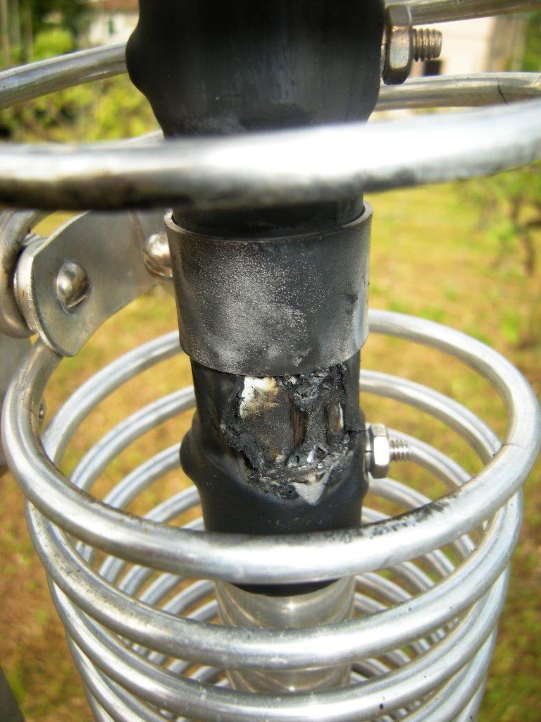
Lightning in the sky !
As
mentioned previously an antenna weakness, as also indicated by the installation
manual in troubleshooting section, is the danger of arc discharges between
pipes and locking strap supporting 40/80m coils.
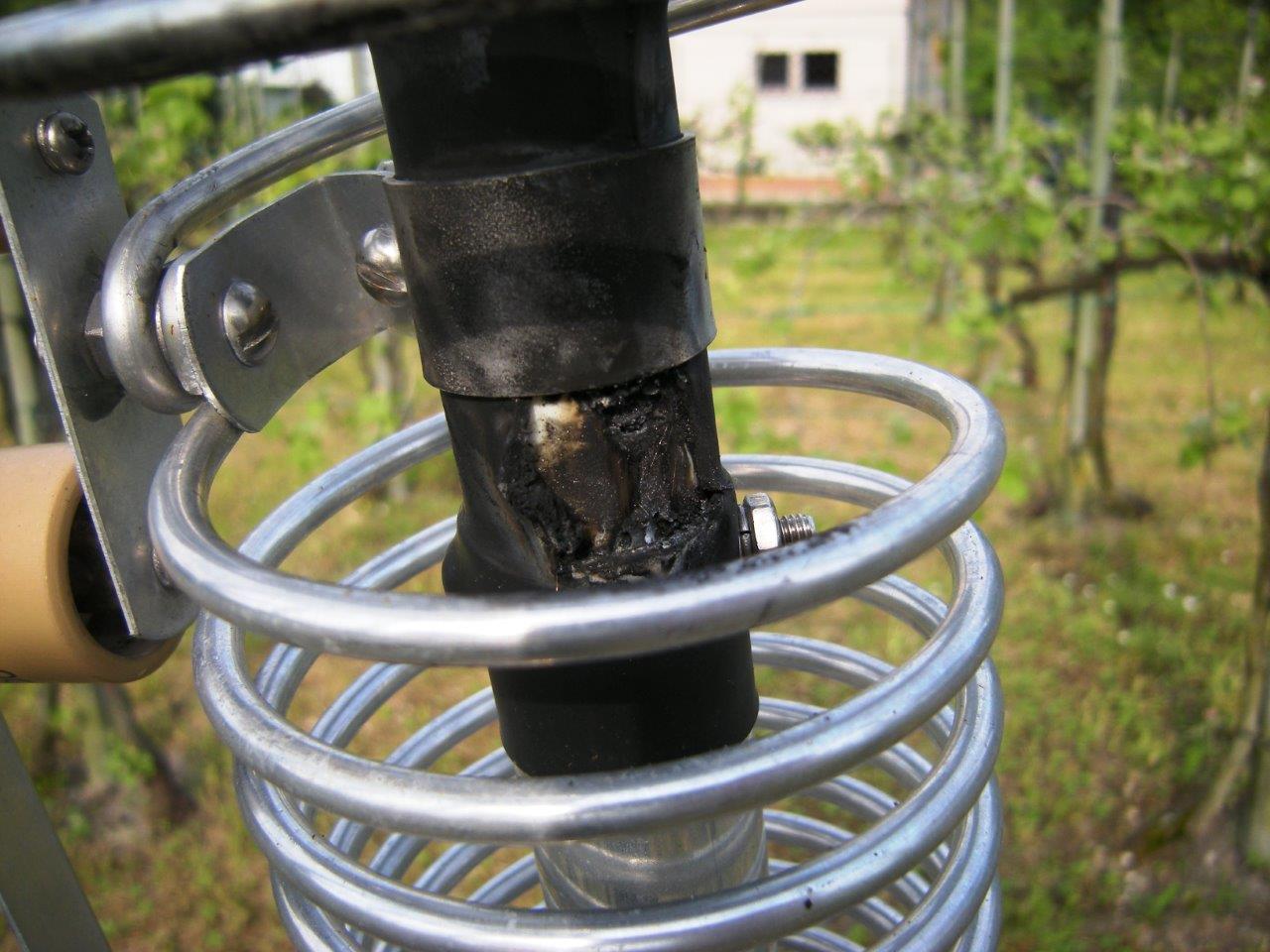
After few weeks, testing an amplifier on 30mt, applying the power of 1.5 kW CW
key down this phenomena was presented.
The discharge produced a large burning with carbon residue which provided a further
path for RF
Here, therefore, any further high power transmission
produced an eye-type effect like arc welder.
This is insulator shoot inspected the following day:
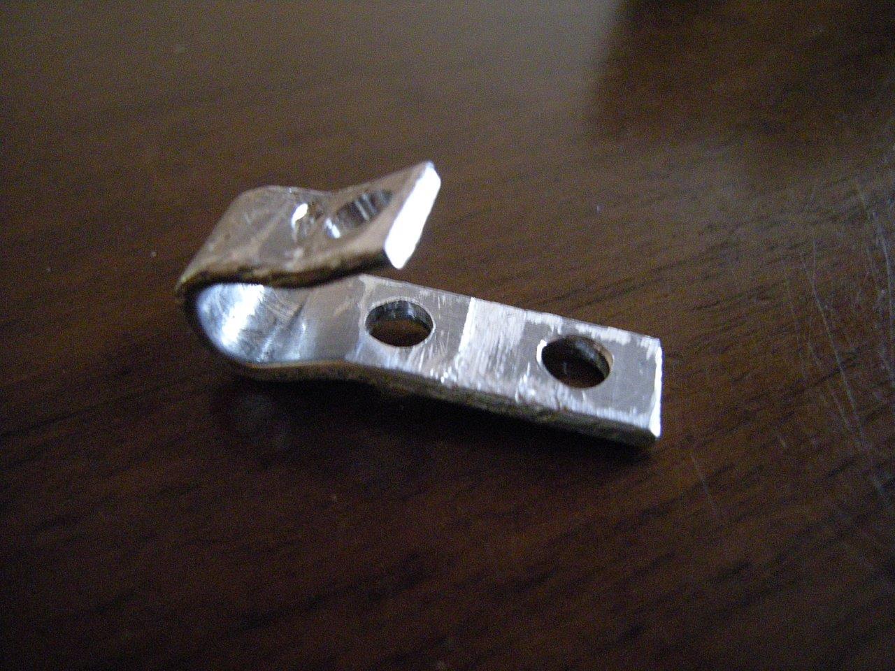
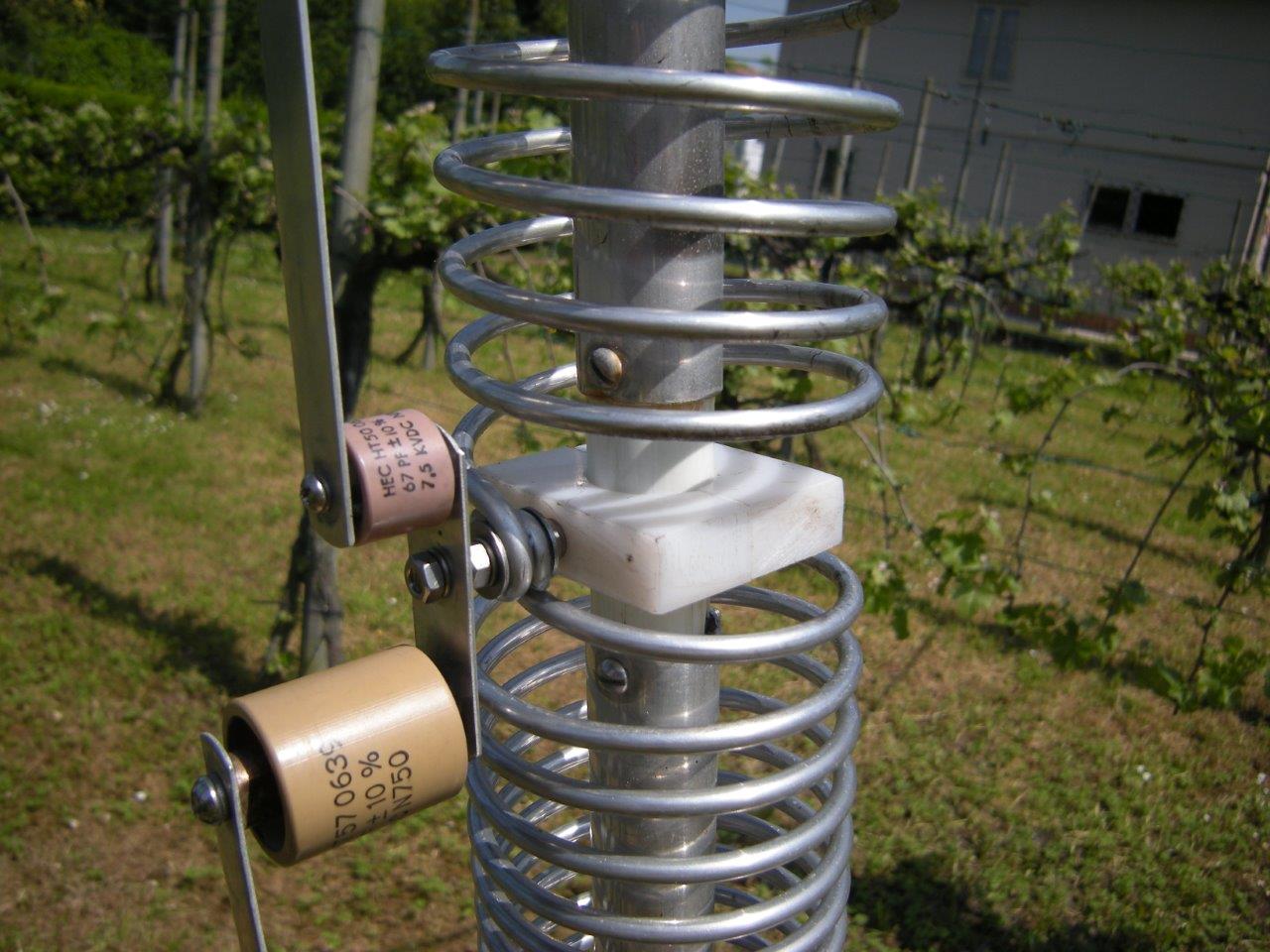
Solution
provided by manual is simple cleaning routine and maintenance (!?!?) but to
avoid the problem reappears I've radically eliminated the cause.
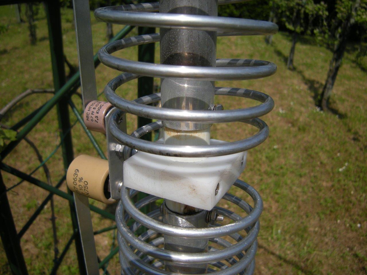
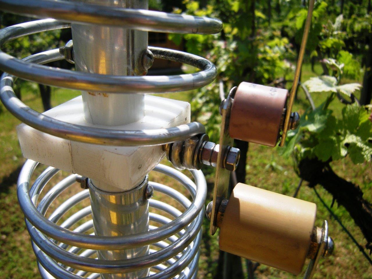
A polyethylene insulating support has been built to replace the incriminated aluminum strap.
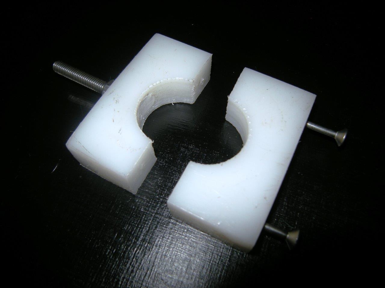
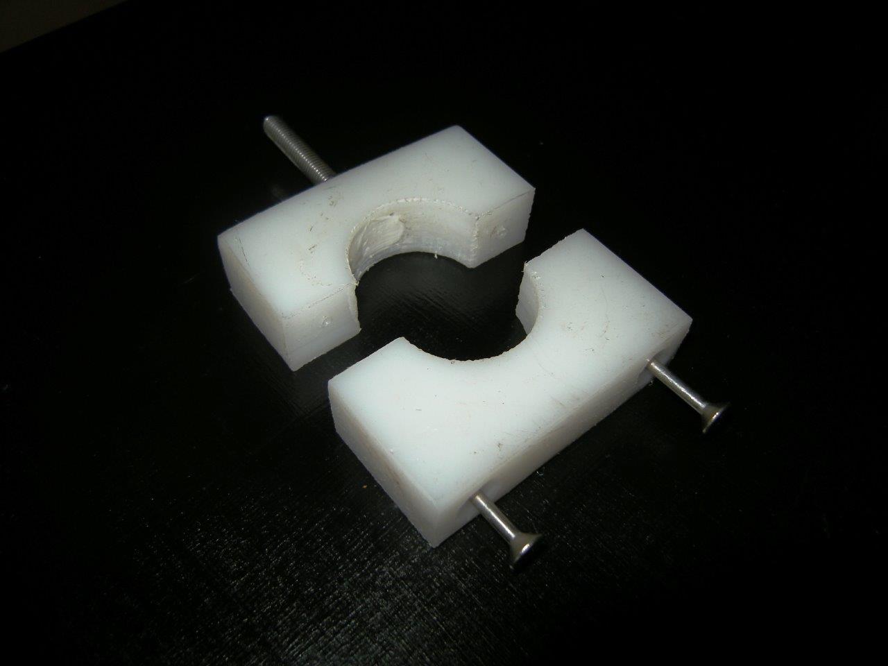
Inner
diameter is
This way, distance between high RF potential points has been greatly spreaded.
Conclusions
The final
conclusions I have drawn from this experience can be summarizes by these
points:
A vertical antenna allows surely to work anywhere on the planet, remembering
that propagation will always be the dominant element on a radio contact.
The vertical has as advantages the relative installation simplicity
due to single radiating element,
weight and size are usually reduced, also has a low angle of radiation, making
it an excellent device for DX, does not need rotor.
As contrast, the vertical antenna have not the peculiarity like yagis to "amplify" the transmitted and received signal
toward a particular direction, nor can't attenuate signals from unwanted directions,
which could interfere with the signal required or cause, if very strong, receiver
intermodulation.
I remember on other hand, that in mathematical terms 6dB gain correspond to
doubling voltage that means to quadruple the transmitted (or received) power then, being the
normal S-Meter calibrated to 1 S point increasing every 6dB, feeding a certain
power to a vertical (with 0dB gain unit), will produce in the receiver S-Meter a deflection of 1 S point less than the
same power fed to a Yagi with 6dB gain.
The difference between the two types of antenna therefore is not so striking as one might think.
The vertical is noisy on reception, especially in low bands, where DX signals
are often covered by electrical noise coming from artificial sources of
classical human settlements (engines, lamps, controllers, electronic devices -RF
and not-, etc.) which have a predominantly vertical polarization.
Then, realization of dedicated antennas for reception on these bands (magnetic
loops, flag, pennant, dipoles, etc.) is highly recommended.
Verticals can also lead to a considerable work if installed very elevated with resonant
radial, especially if in uncomfortable and very high positions, because of the
difficulty to implementing the artificial ground plane.
However I conclude with the statement that, of course, having the chance, the
installation of large directional antennas on large towers would be surely
preferred but with awareness of the available resources, the vertical antenna together
with its installation accuracy is a great tool to be able to compete against
more "important" antennas, and break the most avid pile-ups, giving
you with pride a lot of satisfaction.
Upated August, 10 2011
:
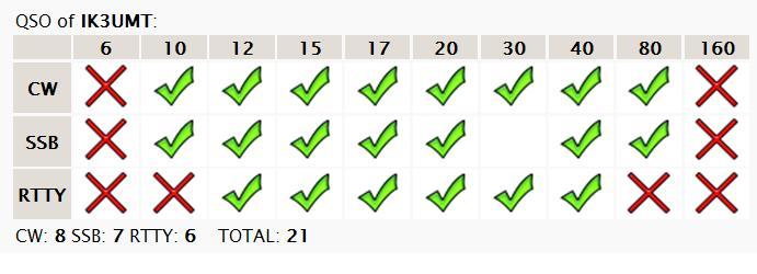
This country is easy to work from my locator, but pile-ups were huge,
Not bad for a 10ft height antenna in urban environment...!!!
Please , feel free to
contact me for any question : ik3umt@ir3ip.net
UPDATED
SEPTEMBER 10th 2009 :
73 de Federico
IK3UMT